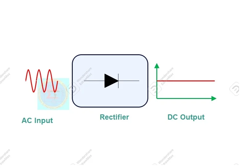
Concept of halfwave rectifier
A halfwave rectifier allows half cycle of each complete cycle of an AC supply flow through it. It passes unidirectional direct current for one complete half cycle only. Another cycle will be restricted to pass through it. So current always flows one direction only for each half cycle period.
A half wave bridge rectifier is an electronic circuit which allows unidirectional current to flow through load during only one-half period of a complete one input AC cycle.
An Alternating supply has two half cycle in each cycle. They are positive and negative cycle. A halfwave rectifier will conduct only either positive half cycle or negative half cycle according to diode configured in it.
If diode anode connected with input (Vin) Ac supply it will conduct positive half cycle. On other side cathode connected with input (Vin) AC supply, then it will conduct only negative half cycle only
Please note that a semiconductor diode will conduct electric current , when it is forward biased only
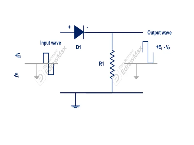
Circuit Diagram
A halfwave rectifier consists single PN junction diode connected with load resistor in series connection.
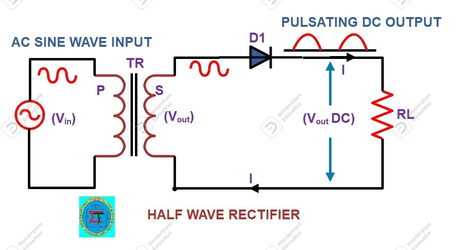
A stepdown transformer used to reduce voltage level according to requirement of load voltage(Tr). Input supply connected with transformer. Secondary of the transformer connected across combination of diode (D1)and load resistor (RL). The transformer also great advantages for isolation of high voltage from rectifier circuit. It also prevents human from experiencing any kind of electrical shock.
With help of above setup high voltage applied to primary of transformer and rectified DC supply can be received at load resistor(RL) Terminal.
Operation of halfwave rectifier
When we apply input AC supply transformer stepped down magnitude of voltage level. But same frequency available across rectifier diode. During positive half cycle diode (D1) becomes forward biased. Until it overcome barrier voltage diode would not conduct current. Once it reached above barrier voltage diode starts to conduct and current flows from anode to cathode as shown in figure.
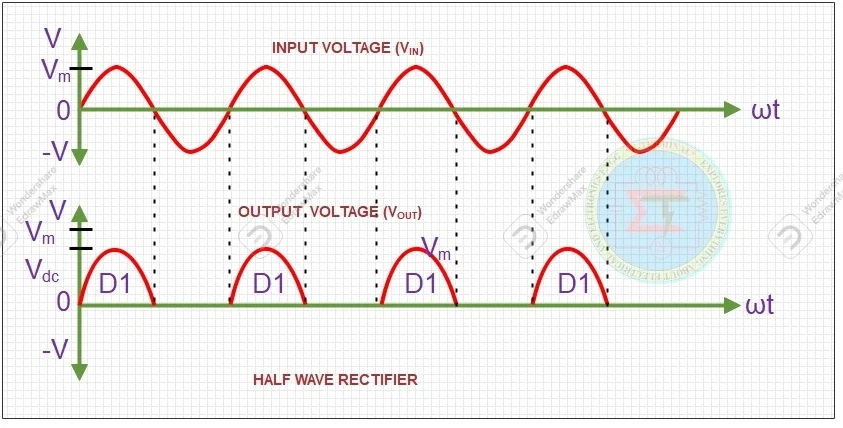
The output current in positive side will increase till it reaches maximum value of supply voltage. After circuit current starts to reduce and diode will be in conduct state up to positive half cycle reaches zero. After it starts to increase in negative direction. But diode (D1) becomes reverse biased. Its depletion layer also starts to increase. So, current does not flow in circuit.
Minimum voltage required to cross over rectifier diodes
For Silicon =0.6 V (Conducts on 0.7 V).
For Germanium = 0.2V ( Conducts on 0.3V)
So, during positive half cycle current utilized in electrical circuit. Remaining period it will be OFF. Please refer below waveform , shows conduction state of half wave rectifier
But a halfwave rectifier cannot be simply made just connecting a single diode with circuit. There below mentioned parameters to be followed for its satisfactory operation
Peak Inverse voltage (PIV)
Every load may be different voltage level for their operation. So rated voltage of load will be applied across rectifier circuit. During diode conduction state , there is no voltage drop across diode. When diode becomes reverse biased full supply voltage appear across diode. Hence it must be considered that , diode should capable to with stand it. It is also called as peak inverse voltage(PIV)
Peak inverse voltage defined as a diode can withstand maximum reverse bias voltage without damage of its PN junction.
It is equal to maximum voltage of negative half cycle (Vm)
Peak inverse voltage (PIV) = Vm
Vs = Vm sin ωt
Ripple Factor
Output wave form of rectifier will be pure DC wave form. It contains AC components in it.
It is defined that ratio of RMS value of AC component to the DC component in the rectifier output
Ripple factor (r)= RMS value of AC component / DC value of output voltage
r = Vr RMS / Vdc
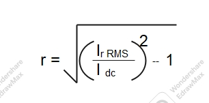
Ripple factor of halfwave rectifier is 1.21% to 121%.
Rectifier Efficiency
Rectifier efficiency defined as ratio output power delivered to load to input AC power applied to rectifier circuit.
Efficiency = Output DC power delivered to load / Input AC power applied to rectifier circuit
Maximum Efficiency of a halfwave rectifier is about 40.6%
Transformer utilization factor(TUF)
It is defined as ratio of DC power delivered to load to output AC supply rating of transformer secondary winding.
Transformer utilization factor (TUF) = Pdc rectifier output/ Pac transformer secondary
Ripple frequency
Ripple frequency said as number of ripple pulses present in the rectifier output per second.
A halfwave rectifier ripple frequency is equal to its supply frequency
fr = fi
Advantages of halfwave rectifier
- It is a simple construction
- Compact in size
- Less expensive
- Only single diode required to form circuit.
Disadvantages of halfwave rectifier
- It has excessive ripple factor
- Low efficiency
- Low transformer utilization factor
- Secondary winding of transformer gets saturated as DC current flows through it
- It can ve used for low range DC circuit only
- Higher filter component required.
Application of halfwave rectifier
It is mostly used where low-cost power supply required such pocket radio, small size battery charger etc.,
Related posts for you:
 Rectifiers an introduction
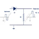 Series Clipping circuits
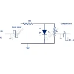 Shunt Clipping Circuits
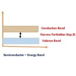
 Semiconductor an Overview
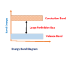 Energy Band for Conductors Insualtors Semiconductors
 Semiconductors Questions and Answers Part-I
 Intrinsic Semiconductor
 Semiconductor Materials
 Accuracy and Precision in the instrumentation
 Block Diagram of Instrumentation System