This article will explain in detailed explanation about 8051 microcontroller block diagram. We have seen many version of micro controller now days. But , it is important to note that 8051 micro controller is basic for all advanced versions. So everybody must know about this 8051 micro controller before study other versions.
Introduction about 8051 micro controller
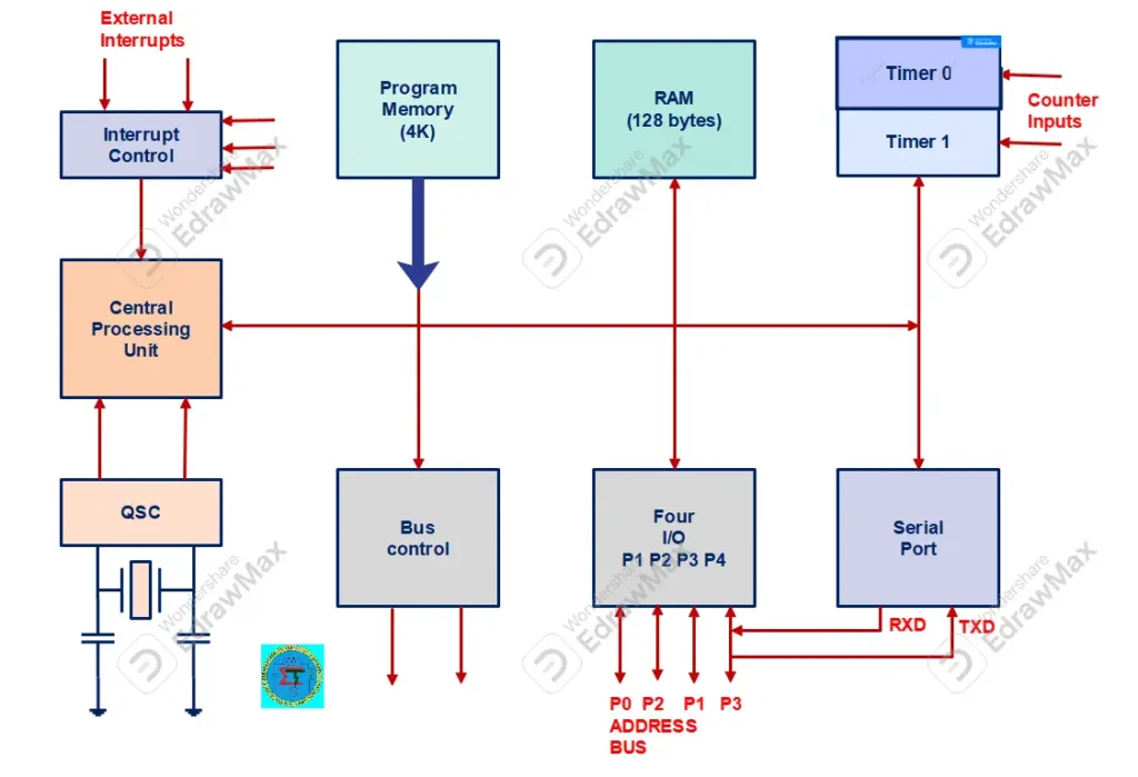
This 8051 micro controller is designed by intel company in 1980. It designed in based of Harvard architecture used in embedded system. The 8051 microcontroller block diagram is shown below. This divided into various parts as various parts. Let us study in details.
Important part of 8051 micro controller block diagram
- Central processing unit
- Interrupt control
- Memory system
- Timers and Counters
- Input and output ports
- Bus control system
- Oscillator circuit
These above parts are divided into internal architecture of 8051 micro controller. These are explained as follows
Central processing unit
The central processing unit simply said as CPU. This is brain of micro controller system. It used to execute instructions and control operations by providing proper timing and coordinates the execution of instructions. This CPU integrated with control unit (CU) and arithmetic and logical unit (ALU) and registers. The control unit controls instructions and ALU performs arithmetical and logical operations. Register used to store temporary data while executing instructions.
Interrupt control
Interrupt control in micro controller used to interrupt current operations. It may be understand as , while micro controller performs one operation, it shift to another operation based upon interrupt response given to it. This service also called as interrupt routine service (ISR). This interrupt control is very useful for emergency operations. The 8051 micro controller designed such a way that, it stops execution of current operation temporarily, when interrupt occurs. This interrupt operation will occur , till interrupt routine service completed. Then micro controller return back to normal operation as usual. The 8051 micro controller has five interrupt sources as listed below
- Timer 0 interrupt
- Timer 1 interrupt
- Serial port interrupt
- External interrupt 0
- External interrupt 1
Memory System
The memory system is used to store program data and user data. The memory has ability to hold the information for processing and provide output after processing completed. The memory system can be divided in to two parts
- Primary memory
- Secondary memory
Primary memory fabricated using silicon chip and integrated chips. It is also can be known as semiconductor memory. Further it classified into RAM (Random access memory) and ROM (Read only memory). This primary memory stores data , which currently being used by 8051 micro controller. Secondary memory used to store user data in permanent ways for longer time. So it can be retrieved later. Magnetic tape, CD ROM, DVD are knowns as secondary memory devices.
Timers and Counters
8051 micro controller has two 16 bit timers (or) counters. The counters are divided into 8 bit registers. The timers are used to measure time intervals to determine pulse width etc.
Input and output ports
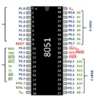
Micro controller is an embedded system to control the operation of machines. Therefore to connect it with machines, devices and other peripherals, input and output ports are very important. So it can accept external inputs for operations and give proper output to control machines etc. To do so 8051 micro controller has four input output ports. Each port has 8 nos pins to connect with external circuit.
- Port 0 – (as well is address bus AD0 to AD7)
- Port 1 – only input output port
- Port 2 – as well as address bus AS8 to AD15
- Port 3 – It also configured with external interrupts
Bus Control system
Bus is group of wires or conducting tracks, used to transfer same kind of signal to other part of circuit of withing micro controller such data and address etc. The size of the bus is ranges in 8 bit, 16 bit, 32 bit and 64 bit. There are two kind of bus used in micro controller system
Address Bus
8051 micro controller has 16 but address bus used to transmit address of the memory locations from CPU to memory
Data bus
It has 8 bit bi directional data bus used to carry data to memory to CPU and vice versa.
Oscillator circuit
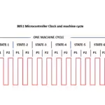
It is important in every micro controller operations. Because every micro controller needs clock signal for its operation. Because it is programmable device and will be programmed based on clock frequency. 8051 micro controller has on chip oscillator which act as a clock source for CPU . The output of the micro controller is stable , because oscillator circuit provides stable frequency synchronize with all parts of micro controllers.

