An Instrumentation system need various element for its proper function from read the physical quantity to measure quantity observed by observer or end user. Each element has function its designated function which is need to be for complete process of instrumentation system. According to function of instrumentation system it is classified as follows,
- Primary sensing element
- Variable conversion element
- Variable manipulation element
- Data transmission element
- Data presentation element
Please refer below instrumentation system block diagram,
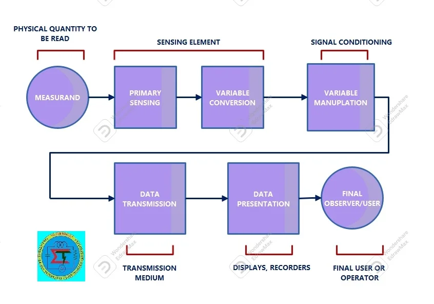
1.Primary Sensing Element
It is prime element of instrumentation system comes to contact directly or indirectly with physical quantity need to be read. Physical quantity means temperature, pressure, humidity, speed, flow etc. This element gets energy from physical quantity and convert it into appropriate quantity which can be processed by next elements.
Example:
Thermocouple converts temperature into electrical signal
Burdon tube pressure gauge converts pressure into dynamic motion form.
2. Variable Conversion Element
This element has responsible converted mechanical/ non electrical signal into electrical form such 1-5 V dc, 4-20 mA. Because non electrical signal received from primary sensing element into suitable electrical form suitable for variable manipulation element.
It is noted that every instrument need not this element. Because many physical instrument like temperature sensors convert signal into direct electrical form.
3. Variable Manipulation Element
This element known as heart of instrumentation system. Because it is important function process received electrical signal from primary sensing/variable conversion element. So that signal can capable to be transmitted to destinated end and remove unwanted signal, improve accuracy etc. Further this signal can be handled by displays and recorders. Variable manipulation element is comprised with signal conditioner circuits
4. Data Transmission Element
This element used to transmit conditioned data from variable manipulation element to data presentation element. This element responsible from sensor located in remote location to control room. The signal can be transmitted by wired or wireless method.
5. Data Presentation Element
It is final stage where processed electrical data can be visually interpreted by operator or user. This element available in control room. So that user can see actual process of the system under observation. Data presentation element presents data in both analog and digital form. In analog form electrical data converted into pointer movement and in digital form it displays using suitable display instruments
Related posts for you:
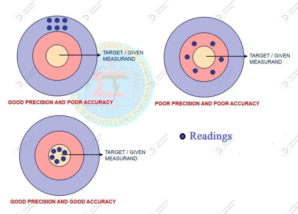
 Accuracy and Precision in the instrumentation
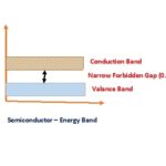
 Semiconductor an Overview
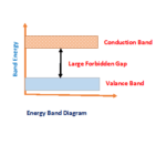 Energy Band for Conductors Insualtors Semiconductors
 Semiconductors Questions and Answers Part-I
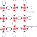
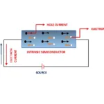 Intrinsic Semiconductor
 Semiconductor Materials
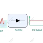 Rectifiers an introduction
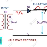 Half Wave Rectifier
 Effect of the Heat and Light while movement of electrons in semiconductor
 Conductivity in the Semiconductor