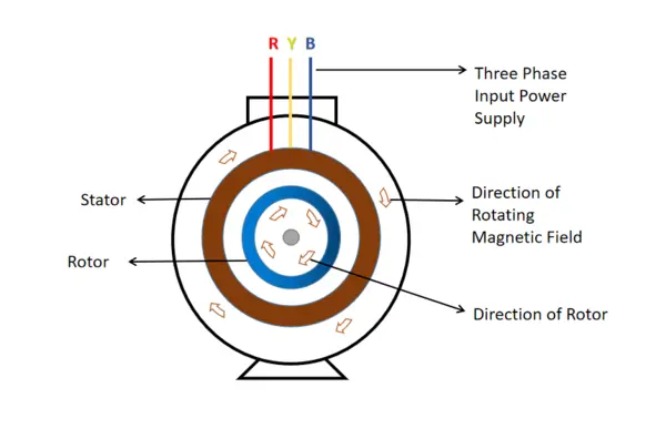
This article made to clear about working principle of operation of an induction motor. As we know that an induction motor consists two types of major parts, one is Stator and another one is rotor. Stator is a stationary part of the motor which made winding by copper conductor. Rotor is rotating part made short circuited winding made with aluminum or copper bars depending upon rating of the motor. The rotor winding is short circuited by end rings. On other hand another type of motor which rotor wounded with copper winding as like as stator.
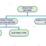
So, we classify that there are two major types of motor widely used
- Squirrel cage induction motor.
- Slip ring induction motor.
1. Power supply Connection of the induction motor
Before we go to study about principal operation let us outlook that, how electrical connection are made with induction motors.
1.1 Squirrel cage induction motor
In squirrel cage induction input power supply voltage directly connected with stator winding through terminal box. There is no input power direct supply connection with or winding terminal extracted to outside of the motor.
1.2 Slip ring induction motor
In slip ring induction motor, input power supply voltage connected with stator winding through its terminal box. Further rotor winding terminal has been taken out to connect with external rotor resistance.
2. Working Principle of the induction motor
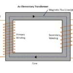
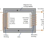
The electric motor is same as a transformer , but it has rotating parts , where transformers are having only stationary parts. So, it clears that an induction motor also uses Faraday’s laws of electro-magnetic induction.
Faraday’s Electromagnetic Induction
“ When a conductor is kept in varying magnetic field its magnetic flux lines are cut by that conductor , so an EMF induced in it.”
Lenz’s Law
“As per Lenz’s law current induced in the conductor kept in magnetic field oppose the cause which produced it.”
Fleming’s Left Hand Rule
“ When a current carrying conductor kept in a magnetic field a force exerted in it. When thumb, forefinger , middle fingers are kept in right angle position , then middle finger shows direction of magnetic flux lines, forefinger shows direction of current ,induced in the conductor, thumb shows direction of force produced in it ”
Based on above laws such faradays laws of electro magnetic induction, Lenz’s law, Fleming’s Left hand rule operation of an induction will be done. So now let us study in details about principle of an induction motor
- As soon as three phase supply connected with stator winding of an induction motor, current flows through its stator winding. The magnitude of the current depends upon the impedance of the stator winding
- The current flowing through motor’s stator winding set up an electromagnetic filed in it.
- This magnetic field with constant amplitude distributed in between air gap of the rotor. This magnetic field are look like phase amplitude of each phase current flowing through stator winding. Further it is look like rotating in the nature. So, it is called as rotating magnetic field (RMF)
- The speed of the rotation of rotating magnetic field depends upon no. Of poles (P) and supply frequency (f). The speed which rotating magnetic field rotates called as synchronous speed
Synchronous Speed (Ns) = 120f/P
- At initial condition rotor is in stationery condition. So magnetic flux which passes through air gap cuts by rotor winding.
- So that there is an Emf induced in it. As we seen earlier that rotor wingdings are short circuited, The current flowing through it . Hence force exerted in the rotor winding, which direction oppose to cause to generate it.
- It causes produces a relative velocity between stator and rotor winding. So, rotor starts to rotates and follow the direction of rotating magnetic field.
- The speed of the rotor is depending upon the load which connected with its shaft. In no load condition speed almost equal to synchronous speed (or) rotating magnetic field produced in stator winding.
- As load increases the difference between synchronous speed and actual speed of the rotor also increases.
- It is very important to note that, rotor speed is said that actual speed or useful speed of the motor.
3. Speed of the induction motor:
- In no load condition speed (N) of the rotor approximately equal to the synchronous sped (Ns)
Speed at No load condition Ns =N
- When external mechanical load connected to the shaft of the rotor , the speed (N) reduces , to produce required amount of torque to produce the load. Until motor produce required amount of load torque to drive the load (TL), the reduction of actual speed will happen. Once motor attains required load torque (TL), reduction of the speed stops. Further it shows that difference between synchronous speed and actual speed of the motor also increases. This difference is termed as slip.
- This is working principle of induction motor
4. Definition of slip
Slip is defined as difference between synchronous speed and actual speed of an induction motor

Slip of an induction motor always indicated in percentage.
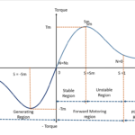
5. Generation of Torque
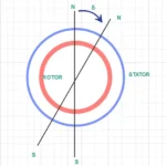
Let assume that rotating magnetic field rotates in clockwise direction. So, rotor also rotates in same direction which slightly less than synchronous speed (Ns) due to its relative motion. On applying Fleming’s right hand rule direction of induced EMF will be outward direction in the rotor. The rotor current generated by rotor EMF produces magnetic field it. The direction of magnetic flux lines produced by rotor EMF opposes the rotating magnetic field flux line (as per Lenz’s law).
So that there is interaction between stator and rotor magnetic field , rotor conductor experience force in it. This force tends them to rotate the armature conductor in same direction I.e. clockwise direction which rotating magnetic field rotates. Hence the torque produced by rotor depends on interaction in between stator and rotor magnetic field.
Change the direction of induction motor
The direction of induction motor always follows direction of rotating magnetic field. The rotating magnetic field direction follows phase sequence of the supply voltage. So, it is clear that we can change the direction of induction motor by changing phase sequence of input power supply connected with it.
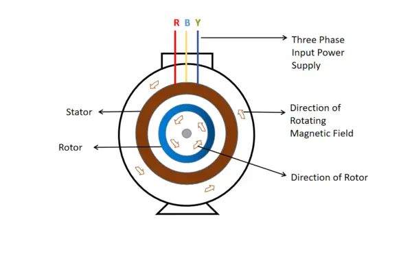
The Phase sequence of the input electrical power supply always denoted as R Y B (or) U V W. by interchanging line in between any two-input terminal , we can change direction of the rotating magnetic field. Which changes the direction of the rotor of the induction motor.
6. Why Synchronous speed and rotor speed always not rotates in same speed?
When motor on no load condition actual speed (N) of the motor in almost equal to the synchronous speed (Ns). It must be noted that actual speed is not exactly equal to the synchronous speed. If both attains same speed I.e. Ns =N , then relative motion between stator and rotor will become zero. Hence there in no current induced in the rotor winding. As there is no flow of electric current torque also not produced. So, motor become stand still. So, it is clearly indicating that relative motion must be present in the induction motor. But we can think that how it is possible at no load condition? Note that rotor winding also has its own mass , which act as fractional load for motor. This rotor weight plays vital role to maintain relative motion between stator and rotor magnetic field. Hence motor continuously rotates.
Related posts for you:
 Torque Equation of an Induction motor
 Torque Slip Characteristics of induction motor
 Synchronous speed and Slip in an Induction motor
Slip Frequency and Induced Emf in an induction motor
Synchronous speed and Slip in an Induction motor
Slip Frequency and Induced Emf in an induction motor
 Introduction to AC induction motors
 Working Principle of Transformer
 Current Limiting Reactors in Power system and Its Types
Construction of the Transformer
Current Limiting Reactors in Power system and Its Types
Construction of the Transformer
 EMF Equation of Transformer