This article will give you detailed explanation about torque slip characteristics of induction motor. Sometime it is also stated as torque speed characteristics. This characteristic can be seen in three parts depending upon operation of the induction motor.
- Forward Motoring
- Plugging
- Regeneration

1. Forward Motoring
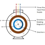
Forward motoring generally known as normal operation condition of the motor. In forward motoring region slip of the motor will be maintained between 0 to 1. it states that Full rpm to Zero rpm of the motor. In this region direction of the rotating magnetic field and rotor direction will be same. When slip S = 0, toque produced by motor will be zero. In other words, no torque will be produced in rotor. Because in slip S =0 condition Ns = N.
Slip S=0
Synchronous speed (Ns) =Rotor Speed (N)
Hence torque produced TL =0 .
Slip S=0 indicates No load connected with rotor. So, torque produced in this condition can be said as no load torque (T0).
When connecting external load , torque increased requirement of torque demand increases. Hence slip (S) also increases.
Once toque reaches maximum torque Tmax at critical slip S= Sm, the torque starts to decrease with reduction of air gap flux. But slip increases along with reduction of flux. To make clearer about it let us divide it into two regions
- Stable region
- Unstable region
1.1 Stable region
In forward motoring condition at stable region shall be in range of 0 ≤ S≤ Sm. This region said as stable region, because torque increases , slip also starts to increases.
The general expression of to determine motor torque can be written as

In stable region slip will be negligible or comparatively low. So sX2 will be negligible while compare with rotor resistance R2.
Where X2 is rotor reactance.
Hence Torque equation ca be re-written as

As rotor resistance always constant , the above equation can be simplified as
T = S
So, in the low slip region Torque (T) is directly proportional to the slip (S). So as torque increases , slip also increases. It causes reduction of motor speed in proportionally or linear manner.
When s = 0 , T =0
As torque increases slip also starts to increases till it reaches maximum slip (Sm).
1.2 Unstable region
Unstable region ranges between Sm ≤ S≤ 1. This region said as unstable , because as torque decreases, slip also starts to decreases. Hence motor speed starts to increases to normal level. In unstable region slip S = Sm to S=1. So, the value of slip is high in this region. As Slip (S) is high, reactance of the rotor X2 also will be high due to SX2 compare with Rotor resistance R2. So, the torque equation of the motor can be modified by neglecting R2.

In above equation R2, and X2 are constant. So, torque is inversely depending on the slip (s)
T = 1/s.
So above equation shows that torque in the unstable region is inversely proportional to the slip. Hence Slip (S) increases , torque starts to decreases.
Maximum Torque (Tmax)
The maximum torque obtained in the induction motor when slip is in maximum I.e. S=Sm. This also called as pull-out torque. The motor will work perfectly till it reach pull out torque. Further increase of the load required torque increases more than pull out, so it falls in unstable region. Hence torque produced by motor also decreases.
If we keep increase continuously when slip S=1 attains motor stops to working (or) become stand still.
2. Generation region
In generation region slip of the motor ranges between S=0 to S=-1. As slip always negative motor rotates always more than synchronous speed in same direction of the rotating magnetic field. The torque also produced in negative direction with motoring region. In generative region motor act as a generator. Hence motor delivers power to the source. The maximum torque in this region can be generated S= -Sm.
3. Plugging Region
Plugging region sometimes called as counter current breaking region. In this region slip of the motor always greater than 1 (1>S). Further direction of Rotating magnetic field (RMF) and rotor will be in opposite. The plugging region made by interchange sequence of any two phase of the motor while running. As motor rotates continuously , due to inertia , rotor is rotating in same direction. In this region ,motor takes very high current, and making high breaking torque by rotor. It is very disadvantages in this region.
Related posts for you:
 Torque Equation of an Induction motor
 Working principle of Induction motor
 Synchronous speed and Slip in an Induction motor
Slip Frequency and Induced Emf in an induction motor
Synchronous speed and Slip in an Induction motor
Slip Frequency and Induced Emf in an induction motor
 Introduction to AC induction motors
 Working Principle of Transformer
 Current Limiting Reactors in Power system and Its Types
Construction of the Transformer
Current Limiting Reactors in Power system and Its Types
Construction of the Transformer
 EMF Equation of Transformer