This article explains about how EMF (Electromotive force) equation of transformer. Transformer is an electrical device works in principle of Faraday’s laws of electromagnetic induction. It says that
“When a conductor kept in an alternating electromagnetic field an EMF induced in it.”
“The magnitude of induce EMF in that conductor is proportional to the amount of magnetic flux lines cuts by conductor per second.”
(or)
“The induced EMF in that conductor amount of magnetic field varying per second
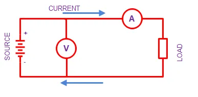
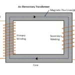
1. Circuit Diagram

The circuit diagram shown in above figure shown, connection of the transformer to find emf induced in it. The primary winding of the transformer connected with rated input alternating current supply. A voltmeter connected across secondary winding to measure emf induced it. When supply given across primary winding of the transformer , current starts to flows through it. It developed electromagnetic field. The electromagnetic field produces magnetic flux lines . This magnetic flux lines will be alternating in nature. Because an alternating input supply given to the transformer. The varying (alternating) magnetic flux gets linked with secondary winding through core of the transformer. So secondary winding cuts these magnetic flux lines and emf induced in it by electromagnetic mutual induction.

Remember that, in auto transformer, both primary and secondary winding are same. So there emf induced in electromagnetic self-induction method.
Further primary winding of the transformer is also a conductor. The same magnetic flux lines link with primary winding, and an emf induced in it too . This is called self-induction.
Derivation of EMF equation in the transformer
The input supply voltage (Vin) given to the primary winding, so that current flowing through it is can be considered as (IP) amperes
The frequency of the input supply (f) Hz.
When current flowing though primary winding , an electromagnetic field induced and it produces magnetic flux lines of φm weber.
The magnetic flux lines sinusoidal form at any instant as input supply. Its frequency is also equal to ‘f’ Hz.
Magnetic flux lines generated at any instant,
φ = φm sin ω t ————-(1)
Where,
Φm = maximum value of magnetic flux lines produced
Φ = magnetic flux lines produced at any instant.
ω = 2πf , where f is frequency of the input supply
According to Faraday’s laws of electromagnetic induction emf induced by varying flux lines linked with secondary winding given as

The above equation is end induced per conductor I.e. N=1at any instant. Let substitute expression of magnetic flux lines induced there at any instant (Eq: 1) at (Eq: 2)
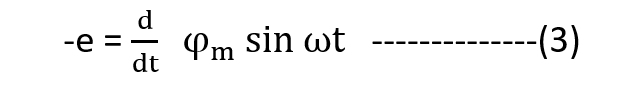
By deriving above in terms of derivation
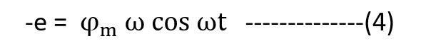
By applying cos ω t = +/- 1 , we get maximum value induced in the per turn(N).
emax = ω Φm
emax = 2πf Φm ————–(5)
But transformer winding wounded with N no. of conductors. So maximum value of emf induced int it
emax = 2πfN Φm ————–(6)
The above equation number (6) expressed in maximum value of emf induced in a winding. In practical we use RMS (root mean square) value.
So, RMS value of emf induced in N turn is


Final expression of EMF induced in Transformer
Let assume that voltage induced in primary and secondary winding are E1 & E2 respectively
They expressed as below,
E1 = 4.44ΦmfN volts ————(8)
E2 = 4.44N ΦmfN volts ————(9)
The both above equations 8 and 9 are represents emf induced in primary and secondary winding respectively
Related posts for you:
 Working Principle of Transformer
 Construction of the Transformer
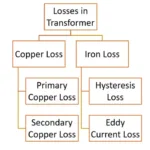 Losses in transformer
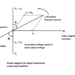 Ideal transformer
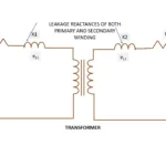 Leakage Reactance of transformer
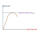 Efficiency of Transformer
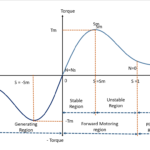 Torque Slip Characteristics of induction motor
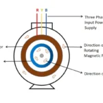 Working principle of Induction motor
 Classification of Transmission lines