Network Terminology
Electrical network made by interconnection of various elements like source, load resistances, control switches etc. While study Electrical network various types of terminology used for it. Let us study about these in details here. They are listed below,
- Active elements
- Passive elements
- Node
- Junction
- Branch
- Loop
- Mesh
These terminology plays vital role while solving simple and complicated network problems. So, it is very necessary to know about these terms.
1. Active Elements
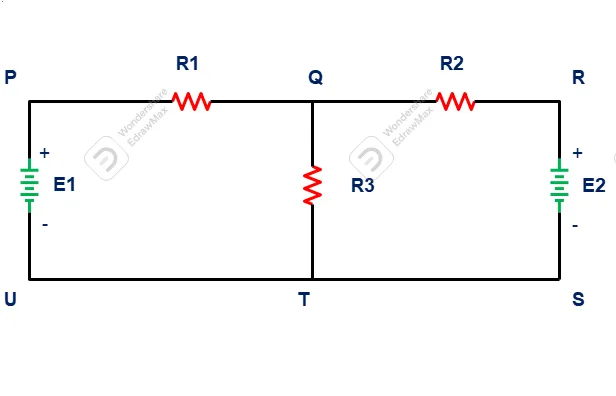
Active work is very important to a circuit to provide electrical energy to it. A network contains various kind of active element such battery, generators. In circuit E1, E2 are active elements, they are providing electrical energy to circuit.
2.passive Element
A network is made for purpose to utilize electrical energy. Hence it it important that few or more elements are to connected in a electrical network to utilize energy supplied by active elements. Passive elements may be resistive, inductive, capacitive. Mostly in DC networks contains resistive elements, whereas AC networks are connected with resistive, inductive as well as capacitive elements.
3. Node
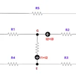
Node is defined in an electrical network defined as two or more network elements (they may be active or passive) joined together. In network P, Q, R, S, T,U are identified as node.
P – source E1 and Resistor R1 connected together
Q – Resistor R1, R2, R3 are connected together
R – Resistor R2, Source E2 are connected together
S,T,U – Source E1, E2, Resistor R3 are connected together
4. Junction
Junction in an electrical network identified as where two or more elements are connected together. In above circuit Q and T are identified as junction.
Q- Resistor R1, R2, R3 are connected one another
T- Resistor R3, Source E1, E2 are connected with one another.
5. Branches
Branches in a circuit is where separate closed loop made and current are separated or together through same junction. In Above circuit diagram junction Q where In Above circuit diagram junction Q where current delivered from sources E1 and E2 through resistor R1 and R2 respectively. The combined current , then flows through resistor R3 Separates again towards E1 and E2 sources.
PQT, QTU – Branches 1 which belongs to circuit QRST
RQT, QTS – Branches 2 which belongs to circuit PQTU
6. Loop
A closed-circuit path in a circuit which allows to flow current in called as loop.
PQRSTU – Loop-I ( E1-R1-R2-E2)
PQTU – Loop-II (E1-R1-R3)
RQTS – Loop-III (E2-R2-R3)
7. Mesh
A mesh in an electrical circuit which cannot be further subdivided into loop. In diagram PQTU, RQTS called as loop.
Related posts for you:
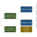 Electrical Sources (Voltage and Current Source)
 Kirchhoff’s Law – Types, Definitions, Functions
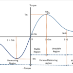 Torque Slip Characteristics of induction motor
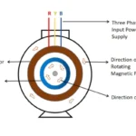 Working principle of Induction motor
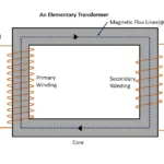 Working Principle of Transformer
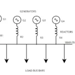 Current Limiting Reactors in Power system and Its Types
 Construction of the Transformer
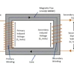 EMF Equation of Transformer
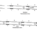 Classification of Transmission lines