1. Current Limiting Reactors – an introduction
This article discuss about current limiting reactors in the power system The entire power system network interconnected with many components like switchgears, Current transformers, Isolators etc. It is most vital condition that switch gears like circuit breakers, isolators should be capable to handling maximum short circuit current at the time of interrupting condition. Otherwise it may damage its contacts and components associated with it. But fabrication of high current contact point also not in economical and might be bulky. So The short circuit current may be reduced by using an external component, to switch gear become more reliable.
In order to control this short circuit current limiting reactors are popularly used. It is a device which connected in series with system, to offer low reactance under normal condition and high reactance under abnormal and short circuit condition.
The coil is designed such it offers very less ohmic resistance compared to its reactance value. Due to very less ohmic resistance, power system efficiency also maintained.
2. Classification of Current Limiting Reactors
The current limiting reactors are classified, according to location connected with the circuit. Basically they are connected in the three locations
- Generators reactors – in series with the generator
- Feeder reactors – in series with the individual feeders
- Busbar reactors – Connected in between busbar system
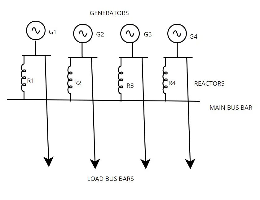
2.1 Generator reactors
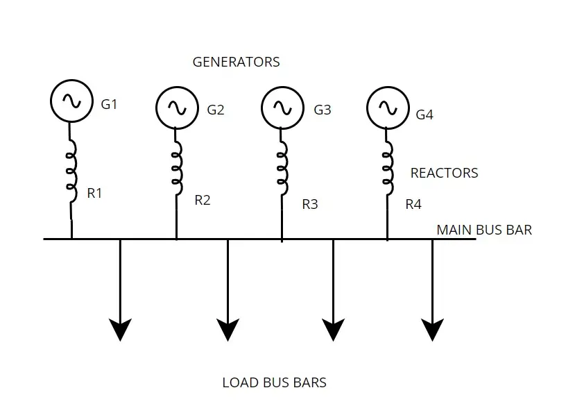
In this configuration current limiting reactors are connected in series with each generator. In case any fault arises in the remaining section of the power system, it prevents generators from the short circuit current flow. But it also suffers by following disadvantages, so that this configuration is not used often.
- If all generators are in parallel operators, then all reactors are connected in the line. So considerable amount of voltage drop taken in that place.
- If fault occurs in the main bus bar, there is possibilities of heavy voltage drop in the main bus bar. So generator may go out of from synchronization
- As generator disconnects from the main busbar continuity of the supply also affected.
2.2 Feeder busbar
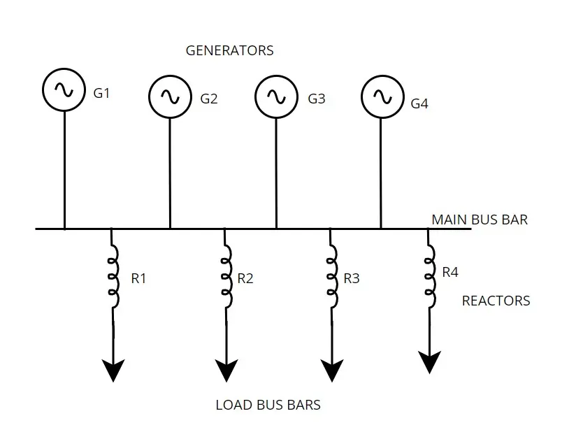
In this configuration reactors are connected in series with each feeder from the main busbar. If any fault occurred in any individual feeder, it does not affect main bus bar voltage and generators. So generators also protected from out of synchronization problem Further it does not affect other feeders in the power system. So continuity of the supply also maintained well. But these also suffers from following disadvantages
- If fault occurs in the main bus bar or generating station , it will not protect system by preventing rise of short circuit current.
- As all reactors are connected always in the line, there is considerable amount of power loss in the system.
- The size of the reactors is directly proportional to number of generators, rating of the generators, and load connected it. It should be fabricated accordingly.
These methods are causes considerable amount of voltage drop in the system. So it affects power system efficiency and increases the losses, so there must be an alternating arrangement to increase power system efficiency
2.3 Bus bar reactors
To overcome disadvantages of the above two configuration reactors are connected in the main busbar of the system. They are
- Ring system
- Tie bar system
2.3.1 Ring system
In ring system, each generators and load bus made as one section and reactor connected between two individual section. This system behave like each load feeder has individual generator. Under normal condition, it provides very less reactance to the circuit. Hence loss in very low. In case of fault arises in any one of the section, either in load bus, of generator, the fault current arises abnormal level. At that time reactor offers very high reactance to flow short circuit current to other sections connected with it. So that particular section only affected. However, this bus bar reactor does not protect generators and load of the faulty section.
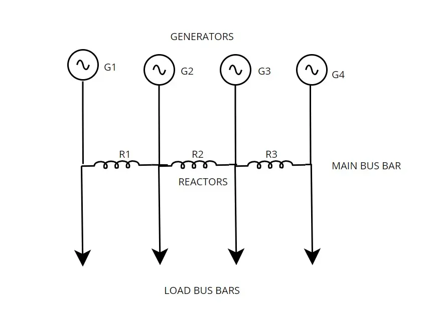
2.3.2 Tie bar system
It is an upgraded design of the ring system. The generator is connected to the main busbar through an individual reactor. But feeders are directly connected with the generator. By adopting this system, voltage regulation between the system has been improved. This system is more suitable where new generators are frequently added to the power system.
Even number of sections are increased; the fault current will not increase than certain value. So reactor can be kept in the fixed size. Thus switch gear designed for the system functioning successfully, if any increase of the number of sections
Related posts for you:
 What is Transmission lines and its types
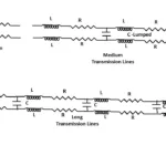 Classification of Transmission lines
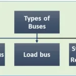 Buses in Power system
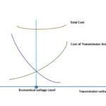 Why high voltage transmission is required
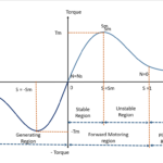 Torque Slip Characteristics of induction motor
 Working principle of Induction motor
 Working Principle of Transformer
 Construction of the Transformer
 EMF Equation of Transformer
 Ideal transformer