Kirchhoff’s law is most useful for formulating network equation. This law can be used where network cannot be simplified by series and parallel resistance equation. Kirchhoff’s works on based on analysis method to solve electrical networks.
Kirchhoff’s law derived by Mr. Gustave Kirchhoff, a German physicist on 1847. He formulated two fundamental law for immense analysis of electrical networks. Those law are
- Point Law (or) Current Law
- Mesh Law (or) Voltage Law
1. Point Law (or) Current Law
In an electrical networks algebraic sum of all branch current meet in junction is zero
Or
In an electrical networks sum of incoming to a junction is equal to sum of current outgoing from same junction
∑ I = 0
Where ∑ represents algebraic sum. Algebraic sum means while sum of all quantity its sign also must be taken into account
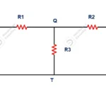
Please refer below figure for analyses about first law (current law (or) point law).
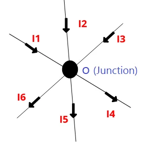
Consider a junction ‘O’ where six number of current carrying meet from different branches. Each conductor carries its current denoted as I1, I2, I3, I4, I5, I6. As per state of Kirchhoff’s law algebraic sum of current in the circuit can be,
∑ I = I1+I2+I3-I4-I5-I6
On other hand
I1+I2+I3=I4+I5+I6
Where,
I1, I2, I3 are incoming current towards junction assumed as positive value
I4, I5, I6 outgoing current from junction assumed as negative value
Mesh Law (or) Voltage Law
It states that algebraic sum of all branch voltage in a closed network is zero
Or
It states that in a closed network sum of voltage drop in individual resistance in equal to sum to sum of voltage supplied by sources connected in it.
Or
It states that algebraic sum of voltage drops in all resistance and algebraic sum of voltage supplied by individual source is equal to zero.
∑IR +∑E =0
∑IR = ∑E
Methods of analysis using second law or mesh law
While solving network equation these below methods need to be followed,
- Mark each junction and node with suitable alphabet order
- Divide circuit into multiple loop as possible. Those loop must contain both resistance and source
- When walk through a selected loop, it must be reached again to starting point.
- If there is fall of potential, then (-) negative sign to be taken.
- If we travel along with direction of current flow and resistance appears, which means fall of potential and vice versa
- While we travel in loop if we go negative terminal to positive terminal of battery then it is rise of potential and vice versa.
- If there rise potential, then (+) positive sing to be taken
- We can walk through in any direction either clockwise or anticlockwise
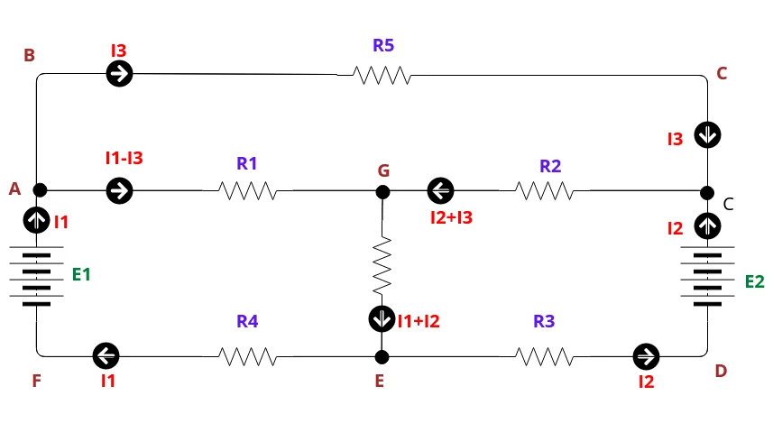
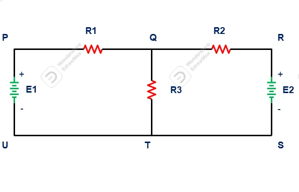
Consider above circuit for better understanding of mesh law. That network developed using resistances (R1, R2, R3, R5) and sources (E1, E2). It can be divided into multiple loop such
ABCDEFA, AGEFA, GCDE. Current can be marked in convenient direction.
Let us look into ABCDEFA loop
In Loop ABCDEFA
- I3 R5 is negative sign because we proceeding along with direction of current flow (-I3 R5)
- There is fall of potential in E2, because we travel from positive terminal to negative terminal of source (-E2)
- There is rise of potential in R3. Because we travel against direction of current flow (I2 R3).
- Again there is fall of potential in R4, because we travel along with direction of current flow (-I1 R4).
- In last there is rise of potential in E1, because we move from negative terminal of battery to positive terminal of battery (E1)
So Equation can be formed as
-I3 R5 –E2+I2R3-I1R4 +E1=0
Or
-I3 R5 –E2+I2R3-I1R4 +E1= -E1+E2
Related posts for you:
 Electrical Network Terminology
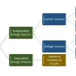 Electrical Sources (Voltage and Current Source)
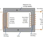
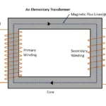 Working Principle of Transformer
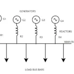 Current Limiting Reactors in Power system and Its Types
 Construction of the Transformer
 EMF Equation of Transformer
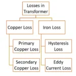 Losses in transformer
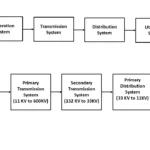 What is Transmission lines and its types
Slip Frequency and Induced Emf in an induction motor
What is Transmission lines and its types
Slip Frequency and Induced Emf in an induction motor