Introduction above Short Circuit KVA
Power systems are affected by various types of faults such as open circuit faults, short circuit faults, and line-to-ground faults. Among these, short circuit faults have the most significant impact on the performance of power system networks. Therefore, it’s essential to consider them carefully, particularly through short circuit KVA in power system calculations
In a power system, all components are vulnerable to short circuit faults. When such a fault occurs, a large current flows through the affected components, potentially causing serious damage. To prevent this, it is crucial to accurately determine the current that would flow under short circuit conditions. Based on these values, appropriate components are selected during the system design process. The rating or capacity of each component depends on the expected level of short circuit current.
However, selecting components purely based on the maximum short circuit current can result in an overdesigned and bulky system. To avoid this, series impedance (Refer Current Limiting Reactors) elements are introduced into the network to limit the short circuit current. These impedances help control and reduce the current that flows through specific paths during fault conditions.
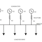
A Simple Network With Fault

For example, if a fault occurs at Point A in a network, the resulting current will naturally flow toward the path with the lowest impedance. Without any series impedance in the generator feeder line, a large surge of current may flow into the generators, potentially damaging them. However, by adding series impedance, this sudden surge is limited, protecting the generators by effectively isolating them from the faulty section.
Under normal conditions, impedances inherently limit short circuit currents to a significant extent. Components such as transformers, generators, and cables also function as effective reactive elements (reactors) in the system. Although these components possess some resistance, the reactance is much more dominant, especially during fault conditions.
In short circuit scenarios, reactance becomes 5 to 10 times greater than resistance, primarily due to the effects of harmonics and frequency disturbances. As a result, resistance is often considered negligible in short circuit current calculations, and the system is analysed primarily based on its reactive characteristics.
Reactance is typically expressed as a percentage, referred to as percentage reactance (%XL).
Definition of Percentage Reactance:
Percentage reactance is defined as the percentage of the total phase voltage that drops across the reactance of a component when full-load current flows through the circuit.
%X =(VphIph)×100
![\[ Percentage of Reactance (\%X) = \frac {V_{drop} }{V_{phase}} x 100 \]](https://eeeterminal.com/wp-content/ql-cache/quicklatex.com-b0e58de32b79e687c0345c088692fc77_l3.png "Rendered by QuickLaTeX.com")
in Transformers and Generators commonly derived as
[\ Percentage of Reactance (\%) = \frac{X_{actual} x I{FL}{V_{rated}} x 100\]
Reactance is typically represented as a percentage, denoted as %X
.Percentage of reactance %X = IX/V x100 [\ \%X = \frac{IX}{V}\]
Here,
I = Full load current under short circuited condition
V = Phase voltage available in power system
X = Reactance connected in circuit Ohm/Phase
Percentage of Reactance in Terms of KVA and KV
The percentage reactance can also be expressed in terms of kVA and kV, as derived from the above equation
By rewriting above percentage of reactance equation
![\[ X = \frac{\%XV}{100I}\]](https://eeeterminal.com/wp-content/ql-cache/quicklatex.com-455f16fd89101b2af54c361581b68a0b_l3.png "Rendered by QuickLaTeX.com")
Multiplying both numerator and denominator by Phase voltage V, we get
![\[ X = \frac{\%XVV}{100VI}\]](https://eeeterminal.com/wp-content/ql-cache/quicklatex.com-9a475fd508547363d2f3a4988d229a49_l3.png "Rendered by QuickLaTeX.com")
By diving voltage parameters in both numerator and denominator by 1000 , KVA can be obtained
![\[ X= \frac{\%X (\frac{V}{1000} x \frac{V}{1000} x1000}{100 x frac{V}{1000}} xI\]](https://eeeterminal.com/wp-content/ql-cache/quicklatex.com-ca2a6adeda61ea849a4657d321830d3f_l3.png "Rendered by QuickLaTeX.com")
![\[X = \frac{\%KV^2 x 10}{KVA}\]](https://eeeterminal.com/wp-content/ql-cache/quicklatex.com-96e77ef5b97bf771c59b24ff99f42060_l3.png "Rendered by QuickLaTeX.com")
![\[ \%X = \frac{KVA x X}{10KV^2}\]](https://eeeterminal.com/wp-content/ql-cache/quicklatex.com-4aa1b044880e3381f31c2474dfc4cdf4_l3.png "Rendered by QuickLaTeX.com")
This equation highlights that the percentage of reactance depends on the system’s KVA rating.
Now, let us assume that X represents the connected reactance in the circuit. Under short-circuit conditions, the short-circuit current can then be calculated as
![\[ I_{sc} = \frac{V}{X}\]](https://eeeterminal.com/wp-content/ql-cache/quicklatex.com-f6a52ab42c27b2f2d49ebab5b5b2cf86_l3.png "Rendered by QuickLaTeX.com")
By substitute the derivation of X in above, we get
![\[ I_{sc} = I x \frac{100}{\%X}\]](https://eeeterminal.com/wp-content/ql-cache/quicklatex.com-e5995d92fe2e8c929aa9257af720c49d_l3.png "Rendered by QuickLaTeX.com")
Why Base KVA Required
In a power system, equipment typically comes with varying KVA ratings. As a result, determining the KVA for each individual component can be quite complex. To simplify calculations, the percentage reactance of all components is expressed using a common KVA rating, referred to as the Base KVA
The percentage of reactance at base KVA = KVABase/ KVARated X % Reactance at Rated KVA
The Percentage of reactance at KVAbase =
![\[ \frac{KVA_{Base}}{KVA_{rated}} x X_{Rated KVA}\]](https://eeeterminal.com/wp-content/ql-cache/quicklatex.com-49edb329bb41492432549c51b51cf0e0_l3.png "Rendered by QuickLaTeX.com")
When a short circuit occurs, the voltage at the fault point drops to zero. It is standard practice to express the short-circuit current in terms of short-circuit KVA, calculated using the normal system voltage at the location of the fault
Short circuit KVA definition
Short-circuit KVA is defined as the product of the normal system voltage and the short-circuit current at the point of fault
It is generally expressed in KVA
As we seen earlier in this article short circuit current Isc = I (100/%X)
Power systems are typically three-phase systems. Therefore, to determine the short-circuit current in a three-phase system
![\[ I_{sc} in Three Phase = \frac{3V x I_{sc}}{1000}\]](https://eeeterminal.com/wp-content/ql-cache/quicklatex.com-95720f26bc8cb6a9a87a985be895210c_l3.png "Rendered by QuickLaTeX.com")
![\[ \frac{3VI}{1000} x \frac{100}{\%X}\]](https://eeeterminal.com/wp-content/ql-cache/quicklatex.com-60bbeba588977531db889d361de650dd_l3.png "Rendered by QuickLaTeX.com")
![\[Short Circuited KVA in Three Phase Circuit = BaseKVA x \frac{100}{\%X}\]](https://eeeterminal.com/wp-content/ql-cache/quicklatex.com-4432d9102c4962ff105f123d0fc254e1_l3.png "Rendered by QuickLaTeX.com")
Related posts for you:
 Current Limiting Reactors in Power system and Its Types
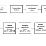 What is Transmission lines and its types
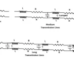 Classification of Transmission lines
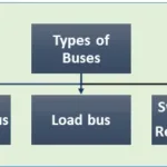 Buses in Power system
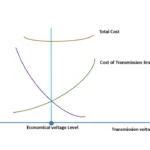 Why high voltage transmission is required
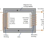 EMF Equation of Transformer
 Temperature co-efficient of Resistance and its behavior with conductors
Synchronous speed and Slip in an Induction motor
Temperature co-efficient of Resistance and its behavior with conductors
Synchronous speed and Slip in an Induction motor
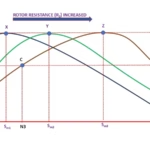 Effect of the Rotor Resistance in a slipring induction motor
Slip Frequency and Induced Emf in an induction motor
Effect of the Rotor Resistance in a slipring induction motor
Slip Frequency and Induced Emf in an induction motor