This article explains about more important terms used in induction motor which are synchronous speed and slip. These characteristics are popularly used. So everyone must to know about it. Let us see in details

Synchronous Speed (Ns) in an induction motor
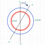
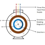
When we give three phase supply to stator of a induction motor, there is an electromagnetic field induces in stator winding. This magnetic field magnitude and direction is similar to the magnitude and direction of the three phase supply in nature. Alternatively it may be assumed as it rotating in a particular direction either clockwise (or) anti clockwise according to phase sequence of the supply connected with it. The speed which induced stator magnetic field rotating known as synchronous speed. This magnetic field called as rotating magnetic field
The input power supply given to stator is an particular frequency. according to it , magnitude and direction of rotating magnetic field changes. In addition to magnetic poles created in coil according to direction of current flowing it. So it clearly shows that , speed of rotating magnetic field is depending upon the number of poles and supply frequency
Let an induction motor stator is having P Number of poles . The frequency of supply voltage is f hz. So synchronous speed can be said as
![\[ N_s = \frac {120 f} {P} \]](https://eeeterminal.com/wp-content/ql-cache/quicklatex.com-b7b49da4a7246c2144107d8fed4e57fb_l3.png "Rendered by QuickLaTeX.com")
As coil in stator is constructed physically it is impossible to change the number of poles. So there is a only one method that supply frequency can be changed to vary the synchronous speed. but changing frequency of supply is also much more hard task and not economical. Generally changing synchronous speed never used in practice.
Slip (s)
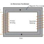
As soon as rotating magnetic field generated in stator its magnetic flux lines are connects with rotor winding. at initial condition rotor is in stalled condition. So the magnetic flux lines are cuts by rotor winding. Hence current circulating in it. This current produces a magnetic field which opposes the causes to induces current in rotor winding. So there is an relative velocity created in it. So rotor starts to rotates in same direction of rotating magnetic field (RMF). But not in the same speed of RMF. Slightly lesser than it. Because the rotor may be connected with external mechanical load . Even there is no load friction and windage losses causes to lesser speed than RMF. So here we can study about slip
The slip is defined as difference between the speed of rotating magnetic field and actual speed of rotor
In other words
The difference between synchronous speed and actual speed of the rotor is called as slip (s)
The slip is always said in percentage of the slip speed.
![\[ Percentage of slip (\%s) = \frac {N_s - N} {N_s} X100 \]](https://eeeterminal.com/wp-content/ql-cache/quicklatex.com-661cc06f75148b8882e17d563275e15b_l3.png "Rendered by QuickLaTeX.com")
(or)
![\[Percentage of slip (\%s) = \frac {\omega_s - N} {\omega_s} X100\]](https://eeeterminal.com/wp-content/ql-cache/quicklatex.com-4a5d552785a127fc306a55df7823bb2e_l3.png "Rendered by QuickLaTeX.com")
So, the actual speed of the rotor can be determined by using equation of slip as
![\[N = N_s (1-s)\]](https://eeeterminal.com/wp-content/ql-cache/quicklatex.com-17fe7df1051e363809d06ccd8e5330d5_l3.png "Rendered by QuickLaTeX.com")
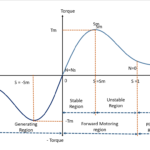
The value of slip always vary between 0 and 1 for motoring operation. Motoring operation means an induction motor working as an normal motor. When motor is stand still slip = 1. i.e Rotor speed is RPM . As same as when Slip =0, motor is almost rotating equal to the synchronous speed. The relation shown in above equation shows that speed is proportional to the slip. When slip increases speed decreases and vice versa. In sometime induction motor may be operated slip value is more than 1. This mode called as plugging. As same as if slip is in negative an induction motor operates as generator
| Slip (s) | Status of Operation |
|---|---|
| s=0 | Rotor RPM (N)is almost equal to Synchronous speed (Ns) |
| s=1 | Rotor is in stand still condition |
| s>1 | Plugging region |
| s <0 (or) s is negative | Generator region |
As this article concluded that synchronous speed and slip in an induction motor are related with each other.
Related posts for you:
 Torque Equation of an Induction motor
 Torque Slip Characteristics of induction motor
 Working principle of Induction motor
 Slip Frequency and Induced Emf in an induction motor
 Introduction to AC induction motors
 Working Principle of Transformer
 Current Limiting Reactors in Power system and Its Types
Construction of the Transformer
Current Limiting Reactors in Power system and Its Types
Construction of the Transformer
 What is Transmission lines and its types
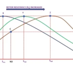 Effect of the Rotor Resistance in a slipring induction motor