positive shunt clipping circuits is device which restricts positive wave form to flow across output devices,
Circuit diagram of positive clipping circuit
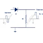
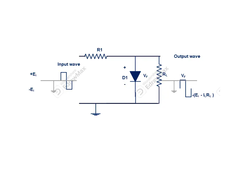
In below figure positive shunt clipping circuit is shown. A diode (D1) connected in series with a current limiting resistor (R1). The output load connected across anode and cathode terminal of the diode. Input signal will be given to the input of current limiting resistor and cathode terminal of the diode. Output signal will be taken out across anode and cathode terminal of the diode (D1).
Working function of positive clipping circuit
When input signal is in negative state (-ve) , the diode (D1) become reverse biased. Hence reverse bias current is very small magnitude flows across diode. So less voltage drops across current limiting resistor (R1). Remaining voltage drops across clipping diode (D1). The same voltage appears across output load circuits which is equal to -E volts.
When input signal become positive wave form, diode (D1) become forward bias. So forward current (IF) flows across diode. The voltage drops across diode will be VF is equal to forward voltage drops. As current flowing though forward bias is high, maximum voltage drops across resistor (R1). In this condition load voltage become equal to the forward voltage drop across diode (D1). Thus it is clearly indicates that , positive halfwave across load is clipped off.
Circuit diagram of negative clipping circuit
In below figure positive shunt clipping circuit is shown. A diode (D1) connected in series with a current limiting resistor (R1). The output load connected across anode and cathode terminal of the diode. Input signal will be given to the input of current limiting resistor and anode terminal of the diode. Output signal will be taken out across anode and cathode terminal of the diode (D1).
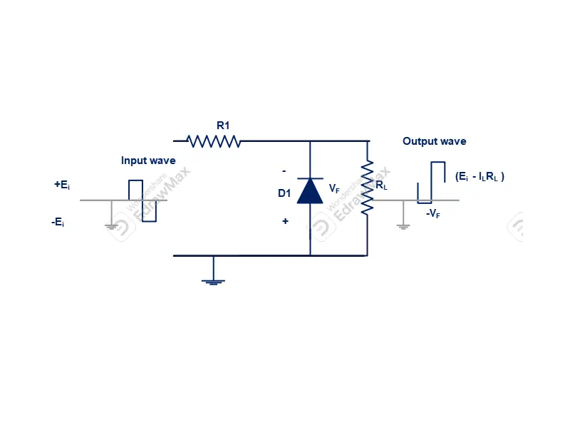
Working function of positive clipping circuit
When input signal is in positive state (+ve) , the diode (D1) become reverse biased. Hence reverse bias current is very small magnitude flows across diode. So less voltage drops across current limiting resistor (R1). Remaining voltage drops across clipping diode (D1). The same voltage appears across output load circuits which is equal to +E volts.
When input signal become negative wave form, diode (D1) become forward bias. So forward current (IF) flows across diode. The voltage drops across diode will be VF is equal to forward voltage drops. As current flowing though forward bias is high, maximum voltage drops across resistor (R1). In this condition load voltage become equal to the forward voltage drop across diode (D1). Thus it is clearly indicates that , negative halfwave across load is clipped off.
Application of the shunt clipping circuits
Shunt Noise clipping circuit
The shunt noise clipping circuits noise are mixed up with peak of both positive and negative waveform. To to so, the signal amplitude must be greater than forwards voltage drop. There are two diodes D1 and D2 are connected bidirectional way. So output waveform is clipped off ± VF . So that noise can be blocked and filtered pure signal will be passed out to output circuit. This type of clipper is widely used with pulse signal , where pulse amplitude is not important.
Biased Shunt clipper
In biased shunt clipper circuit that uses two diodes that have different bias voltage. The cathode of diode that connected with +V bias (VB1), and anode of D2 has a -2V bias (VB2). While input waveform amplitute is less than ±(VB+VF), neither diode is forward biased , and input supply simply passed out to the output voltage. When positive input is greater than (VB1+VF), D1 become forward biased. and output voltage cannot exceed this voltage. Similarly when negative input goes below (-VB1-VF), D2 is forward biased. Hence output is limited to (VB2+VF). The voltage level across resistor R1 is equal to E-Vo
Further amount of current is flowing though resistor is equal to the sum of load current and forward current IF
The output voltage of the biased shunt clipper
Vo = ±(VB+VF)
Biased shunt clipper circuits are mostly used to protect the circuit, where input and output voltage levels cannot be exceed more than certain level.
Zener diode shunt clipper
A Zener diode shunt clipper is works same as biased shunt clipper. But it does not need any biased voltage. In this diode two back to back series Zener diode are connected. When input voltage is sufficient amplitude, diode D1 become forward biased and diode D2 become reverse biased. Further diode D2 enter into breakdown region. At this time output voltage limited to VF+VZ2 . On other hand negative input voltage produces a maximum negative output to -(VF+VZ1)
With equal zener voltages , maximum output volatge is
Vo = ±(VB+Vz)
The voltage appears across resistor is equal to E-Vo and resistor current is equal to IL+IZ

