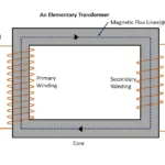
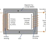
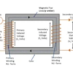
As long as study that flux induced in primary winding in linked with secondary of the transformer without any losses. But in practical scenario it is not correct. There are few amount of flux definitely leaks while linking with secondary winding. If transformer is air core, flux transfer via air medium. On other hand iron core transformer flux transfer through iron core medium. This article will show about what is leakage reactance in transformer
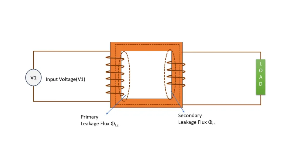
In similar way, when external load current flows through secondary winding , there also flux induced in it. This flux gets linked with primary winding. Few amount of secondary flux also leaks between winding.
These flux are called leakage flux
Let the flux generated by both winding may be denoted as Φ1 and Φ2
Further,
leakage flux produced by primary winding = ΦL1
Leakage flux produced by secondary winding = ΦL2
Both Leakage flux ΦL1 and ΦL2 are in phase with primary current I1 and secondary current I2
It is very important to note that leakage fluxes are not lost in air or core. These flux are definitely gets linked with primary and secondary windings
Hence there are self induced emf is available in both winding of the transformer.
eL1 in self induced emf in primary winding due to leakage flux ΦL1
and eL2 in self induced emf in primary winding due to leakage flux ΦL2
To deliver desired amount of , primary voltage must over come to eL1 , on other hand secondary output voltage must be induced more to over come eL2
So transformer can supply its designed output voltage V2
In conclusion self induced emf eL1 , eL2 are considered as voltage drop inside the transformer
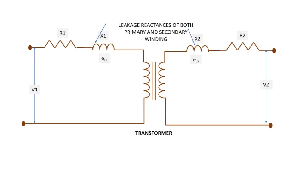
In other words , it assumed that imaginary reactance are connected in series with primary wind secondary windings. These reactance are called as leakage reactance of transformer
Leakage impedance of transformer
Let X1 and X2 are considered as series reactance placed with primary and secondary windings
So,
Primary impedance = Z1 = R1 + jX1
Secondary impedance = Z2 = R2 + jX2
The transfer of impedance takes place on same lines as that of resistors. The transfer of impedance take place from primary to secondary vice versa.

