Introduction
The ideal transformer is a term used to study its characteristics in theoretical study purposes. Because Ideal transformer does not have losses. Power delivered to load in equal to power given to transformer. It also may be said as there are no internal losses in the transformer.
Characteristics of an Ideal transformer
- There are no internal losses occurs inside transformer. Copper loss and Iron losses (hysteresis loss and eddy current loss) are considered as zero.
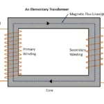
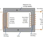
- The leakage of magnetic flux line linking primary to secondary winding is zero. The total amount of magnetic flux lines generated by primary winding links with secondary winding
- As core losses are zero, permeability of magnetic core is very high. So, few current required to generate magnetic flux lines.
- The primary winding has very less amount of resistance. So, voltage drops across it is also zero. The external voltage (V1) applied to primary winding is equal to the back emf (or) induced emf (E1)in primary winding.
External applied voltage (V1) = Induced emf in primary (E1)
- The secondary winding resistance also very few amounts of resistance. So, there is no voltage drops across it. Hence induced emf in secondary winding (E2) is available at external terminal of transformer as output terminal voltage(V2)
Emf Induced in secondary winding (E2) = Output terminal voltage (V2)
- Losses in ideal transformer is zero. So, output power available at secondary is same as input power delivered to transformer
Efficiency = 100%
- The voltage regulation of ideal transformer is zero. Because there are no fluctuations in output voltage depends on different load condition.
Phasor Diagrams of Ideal transformer
On no load condition
An alternating supply voltage (V1) applied across primary winding of transformer. There is no load connected across secondary winding. So, load resistance RL will be infinity. Primary current in ideal transformer must be zero. But small current flows to create magnetic flux line in the core. This current is called as magnetizing current (Im). The amount of primary current flows at no load condition known as magnetizing current of transformer. This magnetizing current magnetize transformer core.

As primary winding resistance assumed as zero (R1 = 0). So magnetizing current lags 90° to the induced voltage in primary winding (E1). The magnetizing current produces sinusoidal shape magnetic flux line (φ) in transformer core. The magnetic flux (φ) is in phase with magnetizing current (Im). The flux gets linked with secondary winding through iron core of transformer. The magnitude of magnetic flux lines links between primary winding and secondary winding are same. There is no leakage flux in the core.

Relation between primary and secondary induced emf
The magnetic flux causes self-induced emf (E1) in primary winding. Its direction opposes the applied voltage (V1). Further Emf induced (E2) in secondary winding , due to mutual induction. There are no load current flows across secondary winding and its resistance also (R2=0). So terminal voltage available across secondary winding is equal to emf induced in it.
Primary induced Emf(E1) = – Input voltage (V1)
Secondary induced Emf (E2) = Output terminal voltage (V2)
The magnitude of induced Emf E1 and E2 are proportional to number of turns available in primary winding (N1) and secondary winding(N2).
E1 α N1
E2 α N2
The emf induced in secondary (E2) is opposes applied voltage to primary (V1). So E2 appears 180° out of phase difference with V1. However, magnitude of secondary Emf (E2) depends on turns ratio K = N2/N1. So primary induced Emf (E1) and secondary induced Emf (E2) appears in phase with each other. But Both are out of phase with input voltage (V1) at 180°.
Power on no load condition
The input power given to ideal transformer is equal to power delivered to load output. There are no losses taking place in ideal transformer.
Let take Input power given to ideal transformer as
P0 = V1ImCosφ0
Where Cosφ0 power factor of ideal transformer at no load condition.
φ0 is phase angle between input voltage (V1) and magnetizing current (Im). As we seen earlier the magnetizing current (Im) lags by 90° to input voltage (V1)
So,
Cos φ0 = Cos 90 = 0
Putting Cos φ0 value in power equation we get,
P0 = V1Im Cos 90°
P0 = V1Im 0
Power at no load condition (P0) = 0
The output power taken by transformer is equal to zero. Hence it has proved that, there is no losses taken in place of inside of transformer
Under load condition
When some load connected between secondary terminals of ideal transformer is stated as transformer under load condition or transformer on load. On load condition external circuit of transformer is become closed circuit. So external load current (I2) starts to flows across load connected with it. The rate of current flow depends on sum of resistance of secondary winding (R2) and load resistance (RL).
Load Current IL α (R2 + RL)
The Load current (IL) lags behind transformer output voltage (V2) by phase angle φ2.

As per Lenz’s law secondary current (I2) will oppose the cause producing it. Hence it opposing magnetic flux lines (φ) produced by primary current (I1). So resultant flux in the core reduced. It is called as demagnetizing effect. This magnetizing effect causes reduction of self-induced emf (E1) in primary winding. As we know that primary self-induced Emf (E1) opposes the primary input voltage (V1). But demagnetizing effect increases difference between input voltage (V1) and primary induce Emf (E1). So additional primary current (I’2) flows across primary winding to compensate the reduction of magnetic flux lines. This called as load components.
Load Component I’2 = I2 x (N2/N1) = KI2
The current I’2 = KI2 is out of phase with secondary current (I2). So, the net primary current becomes phasor sum of load component I’2 and magnetizing current Im
Net primary current I̅1 = ̅I̅2 + Im
So, when load connected in secondary side primary current also increases to fulfil additional demand created to the load.

Reason for increases in primary current when load current increases.
When transformer is under load condition load current I2 will start to flow across load connected in secondary winding. Due to increases of load , secondary load current also starts to increases. . so, Ampere turns in secondary increased (N2I2). This increase secondary mmf will increase the magnetic flux (φ2) generated by secondary current (I2). This secondary magnetic flux lines opposes main magnetic flux lines (φ1). Hence main flux lines decreased and self-induced emf in primary winding also decreases. So, difference between applied input voltage (V1) and self-induced emf increased. To compensate it, additional primary current generated by primary winding (I’2). So Primary current flows in new magnitude of I1 + I’2. This reasons if load increased in secondary winding , primary current also increase
Related posts for you:
 Working Principle of Transformer
 Construction of the Transformer
 EMF Equation of Transformer
 Losses in transformer
 Leakage Reactance of transformer
 Efficiency of Transformer
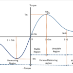 Torque Slip Characteristics of induction motor
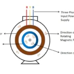 Working principle of Induction motor
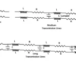 Classification of Transmission lines