This article let us discuss about various types of losses in transformer. When transformer connected with primary input power supply, it transforms and feed to load through secondary winding. But it never supplies output power equal to the input power given to it. Few power losses are happened inside transformer. So, output power is always less than input power.

Output Power of transformer = Input power – Losses
(or)
Input power of transformer = Output power + Losses

The losses are happening inside transformer are classified as below
- Copper loss
- Iron Loss
- Hysteresis loss
- Eddy current loss
1. Copper loss in transformer
Transformer winding having certain magnitude of resistance. While transformer connecting will loads few amounts of power losses taken in winding of transformer. This called as copper loss. The copper loss is always depending upon square of load current. So, it is also known as variable losses.
The power losses in primary and secondary winding are known as primary copper loss and secondary copper loss respectively.
Total copper loss = Primary copper loss + Secondary copper loss
Pcu = P1 +P2
Pcu = I12 R1 +I22R2
Where,
I1, I2 are primary and secondary current
R1, R2 are primary and secondary resistance
So, it is important to keep copper loss as minimum as possible to increase efficiency of transformer. To reduce copper losses winding resistance are must be reduced. To do so high conductivity copper conductors are used.
We know , copper loss is depending on magnitude of square of electric current. Hence it is not proportional to increment at decrement of load.
When Transformer is in full load condition
Full load copper loss = Pcu(FL) = Pcu = I12 R1 +I22R2
Half load copper loss = Pcu(HL) = Pcu = 1/2(I12 R1 +I22R2)
Pcu(HL) = Pcu = (1/2)2(Pcu(FL))
Half load copper lossPcu(HL) = Pcu = (1/4)(Pcu(FL))
2. Iron Losses in transformer
The losses are taken in iron core of transformer said as iron losses. The iron losses are having two components in it. They are
- Eddy current losses
- Hysteresis losses
2.1 Eddy current losses
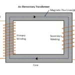
The flux in transformer core is alternating in nature. When it varies with time, these magnetic flux lines are cuts by core also. Hence emf induced it. As core is act itself a conductor , it also provides closed circuit to circulate electric current through it. This induced current is called as eddy current. The power losses happen by eddy current said as eddy current losses.
The core made with silicon steel has finite amount of resistance. So, flow of electric current through core, heat produced. So, the power loss due to eddy current as follows
Eddy current losses = (I eddy current)2 x rcore
The power loss in core (or) heat generated in core decrease efficiency of transformer. So, it needs to be kept to minimum. Hence laminated silicon steel in thickness of 0.35 mm to 0.5mm are widely used in transformer core.
Each lamination of core act as separate conductor with increased resistance. It gradually decreases eddy current in core.
Mathematical expression of eddy current loss
Eddy current loss = KEBm2f2T2 watts
Were,
T = Thickness of core
KE = Eddy current constant
Bm = Maximum flux density
f= frequency of magnetic flux lines/ input power supply
The eddy current loss in frequency dependent. It is directly proportional to square of operating frequency. It can be reduced by laminated core transformer.
2.2 Hysteresis losses
The hysteresis loss in taking in core depends on types of magnetic material used in it. Each magnetic material affected by different magnitude of hysteresis losses. Hysteresis loss depends on are enclosed by hysteresis loop of a magnetic material represents hysteresis loss.
It reduced output power considerable amount. So, efficiency of transformer decreases. To reduce hysteresis loss , the material has smaller area in hysteresis curve preferably used to construct core of transformer. Such low hysteresis area material often called as Lohys.
Hysteresis loss mathematically expresses as
Hysteresis loss = KHBm1.67fv watts
Where,
KH = Hysteresis constant
Bm = Maximum flux density
F= frequency
V = Volume of the core
From above expression, it seems that hysteresis loss is frequency dependent. As increase of frequency hysteresis loss also increases and vice versa.
Related posts for you:
 Working Principle of Transformer
 Construction of the Transformer
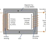 EMF Equation of Transformer
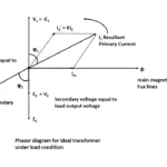 Ideal transformer
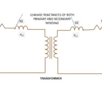 Leakage Reactance of transformer
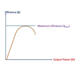 Efficiency of Transformer
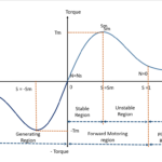 Torque Slip Characteristics of induction motor
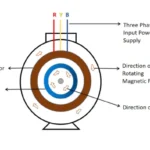 Working principle of Induction motor
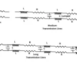 Classification of Transmission lines