We know that Transformer is a static device. Unless induction motor it does not contains any rotating or moving parts. So, construction of the transformer is much simpler than induction motors. In this article let us study about basic construction of a transformer. The transformer may be single phase or three phase. But all have some basic parts its construction.
Basic parts in construction of the transformer
- Electrical Circuit
- Magnetic circuit
- Di-Electric circuit
- Cooling circuit
1. Electric circuit
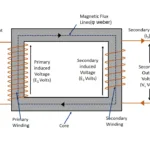
In electrical circuit where current flowing through it , when actual voltage applied and then out from there. There are two main parts in electrical circuits. Primary Winding Where voltage applied to the transformer Secondary winding Where supply taken out from the transformer. In addition to
Auto transformers there is no separate primary and secondary winding. A single winding act as a common for both of them. The wingdings in the transformer made with copper material. Aluminum also used as winding material in recent days. Because aluminum conductor is much cheaper than copper conductor. But volume of the winding will be more, because of large cross section aluminum conductor required to compare with copper conductor. Because copper conductor has more conductivity than aluminum. An aluminum conductor has 60% conducting capacity , while compared with copper conductor.
In large capacity transformer winding are wounded by rectangular shaped conductor for low and high voltage operating conditions. In small and medium capacity transformer circular shaped conductors are mostly used. The winding insulated with enameled layer with varnish impregnated , double layer cotton tape wounded it. Further varnish impregnated paper insulation kept between core and winding of the transformer to protect it from electrical leakage.
2. Magnetic Circuit
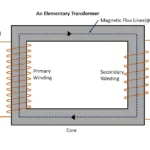
Magnetic circuit of a transformer known as , it provides less reluctance path to magnetic flux line to linkage between primary and secondary winding of the transformer. The core and yoke provided in the transformer are called as magnetic circuit. The magnetic flux generated due to an electro-magnetism in primary winding generates magnetic flux lines. According to Faraday’s laws of electromagnetic induction (working principle of transformer), magnetic flux line induced in primary winding must reach secondary winding to induce an EMF in it. It needs less reluctance path to reach secondary wingdings. So, silicon steel core with high permeability used to provide less reluctance path to magnetic flux lines. Hence magnetic field produced it become very strong.
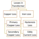
In transformer magnetic field induced in it alternating in nature. So, there are two kinds of losses are taking in the place
2.1 Eddy current loss
The core itself a metal conductor in construction of the transformer. So, when it comes under alternating magnetic field , an EMF induced it. Due to this EMF small amount of current circulating in the core. It increases temperature of the core. These results eddy current loss
- Hysteresis loss
Reduction of eddy current loss
The core of the transformer is always made by laminated thin silicon steel sheet which thickness about 0.35 mm to 0.5mm. So, resistance of the core increases , which reduce current flowing though core . Hence eddy current loss are minimized or eliminated.
2.2 Hysteresis loss
When varying magnetic field strength and magnetic flux density always not attains zero or maximum value at same time. It creates granular vibration in the core. So, temperature of the transformer increases. The loss is depending on area of the hysteresis curve. It is known as hysteresis loss
In addition to few milli-weber magnetic flux lines leakage also will be there. These losses are strongly affecting efficiency of the transformer. So, it must be rectified maximum as possible.
Reduction of hysteresis loss
To reduce hysteresis loss core of the transformer made with less reluctance and high permeability core. It establishes good hysteresis loop
3. Di- electric circuit
Di- electric circuit of the transformer known as insulating medium , which separates conducting parts (Electric circuit) and remaining non conducting part (magnetic circuit). It is most necessary to insulated all parts of the transformer with proper insulating medium. The core is laminated from low voltage and high voltage winding. Synthetic varnish impregnated paper, mica, Bakelite are kept between core and winding of the transformer. Further low voltage and high voltage winding also separated in same method. Higher capacity transformer synthetic impregnated copper tapes are wounded to isolate them from non-conducting parts and other adjacent winding. In dry type transformer normal air or compresses air used as insulating and cooling medium. In oil filled transformer , transformer oil filled to protect winding from moisture and dust. Further it acts as insulating as well as cooling medium.
4. Cooling circuit
In construction of the large capacity transformer cooling is most vital requirement. Because losses are also generating considerable amount of heat in the transformer. It leads damage of insulation. To exhibit heat from transformer , cooling circuits are used. These cooling circuits made with different types of cooling arrangement.
All transformers are generally kept inside of the transformer tank which made with milled steel or high carbon steel. The winding arrangement shall be kept inside of this enclosed tank. Othe cooling accessories, safety equipment, control equipment will be fitted on the surface of tank. Winding leads will be taken out and fitted in the terminal box with appropriate insulating medium.
Types of cooling circuits
- Natural air cooling
- Forced air cooling
- Oil natural air cooling
- Oil natural forced air cooling
- Oil forced air forced cooling
Each cooling circuits shall have their own design parameters and construction.
Along with cooling circuits, breather, conservation tank, Buchholz relay, OLTC, explosion vent, oil level indicator, winding and oil temperature indicator with alarm circuits, radiators, forced cooling fans also shall be used along with transformer.
Related posts for you:
 Working Principle of Transformer
 EMF Equation of Transformer
 Losses in transformer
 Ideal transformer
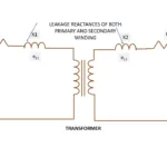 Leakage Reactance of transformer
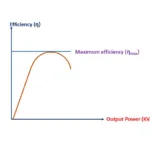 Efficiency of Transformer
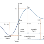 Torque Slip Characteristics of induction motor
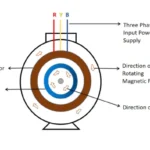 Working principle of Induction motor
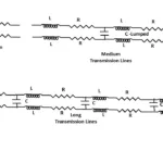 Classification of Transmission lines