In this article , we shall discuss about introduction, types, and working principle of transformer. Transformer became a heart of electrical engineering in modern days. Because every electrical installation is impossible without using transformer in its circuits. The transformer may be connected directly or indirectly with the circuit.
Example:
- In Transmission line transformer connected directly to the electrical circuit
- In residential /commercial installation transformer is connected indirectly (or) before receiving the supply voltage
1. Transformer an Introduction
Before we go to study about working principle of the transformer let us overview about it. Transformer is a static electrical device I. e. It does not contain any moving or rotating part like motor in it. Transformer transfers electrical energy from one circuit to another circuit without electrical coupling. It transfers electrical energy by stepping up / down voltage given to its input. It is very important to note that input and output of the transformer will be alternating quantities (voltage, current) only.

2. Importance of the Transformer
The electrical power transmitted to very long distance to reach consumer utilities. If large amount of current transferred in via transmission lines , losses in the lines will be very high. Which adversely affect transmission efficiency. To increase transmission efficiently losses must be reduced. To do so , transformer connected across the transmission circuit , voltage has been stepped up with help of step-up transformer to desired level. So, line current is reducing gradually. It reduces line losses and increases transmission efficiency. Once it reaches consumer end , transmission line voltage reduced to desired level with help of the step-down transformer.
3. Types of the Transformer
Transformer can be classified according to its construction, working principle,
3.1 According to construction
- Core Type transformer
- Shell Type transformer
3.2 According to voltage level
- Step up Transformer
- Step down transformer
3.3 According to usage in instrumentation circuit
1. Current transformer
2. Voltage Transformer
3.4 According to Installation location
- Power Transformer
- Distribution Transformer
3.5 According to medium of cooling
- Air cooled Transformer
- Oil cooled Transformer
3.6 According to Phase connection
- Single Phase Transformer
- Polyphase Transformer
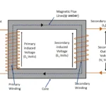
4. Construction of a transformer
The construction of a simple transformer shown here. The transformer has core and two coils are wounded in each side of the transformer. The leads area taken out from the coil to provide and draw out supply from it. The coil is wounded in the high permeability core . Hence it is highly inductive. The core of the transformer is acts as a magnetic coupling path between both of coils. The coil connected to the input supply voltage called as primary winding and another winding where supply taken out called as secondary winding. Normally primary winding connected with input supply, whereas secondary winding connected with external load. It is important to note that , there is no electrical connection between both winding of the transformer. The primary and secondary winding are electrically isolated.


5. Working principle of the Transformer
The Transformer fundamentally works in the Faraday’s laws of electromagnetic induction. The Faraday’s laws of electromagnetic induction said as follows
5.1. First Law
When a conductor kept in the varying magnetic field it cuts magnetic flux lines. Hence EMF induced it. This EMF will be induced as long as there varying magnetic fields are present.
5.2. Second Law
Whenever a conductor kept in a varying magnetic field it cuts magnetic flux lines and an EMF induced in it. The magnitude of the induced EMF is directly proportional to rate of changes in flux lines (or) rate which conductor cuts magnetic field lines
With help of above laws, a transformer works as follows
- The supply voltage connected to the primary winding of the transformer. So current passes through it.
- A magnetic field induced by primary winding due to current flowing through it.
- The magnetic field creates magnetic flux line which connected with secondary winding through magnetic path provided by the transformer core. This magnetic field is varying in nature, because nature of input supply voltage is in alternating in nature.
- These magnetic flux lines cuts by secondary winding, which causes an EMF induced in it.
- If there is an external electrical load connected , a current will flow across it due to secondary induced voltage in the transformer.
Related posts for you:
 Construction of the Transformer
 EMF Equation of Transformer
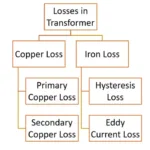 Losses in transformer
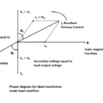 Ideal transformer
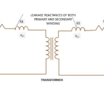 Leakage Reactance of transformer
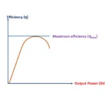 Efficiency of Transformer
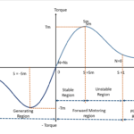 Torque Slip Characteristics of induction motor
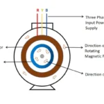 Working principle of Induction motor
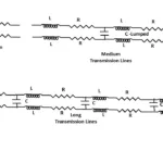 Classification of Transmission lines